EDM Wire Eroder Guide: Types, Working Principle & Selection Tips
2026-08-03
An EDM wire eroder, also called a wire-cut EDM machine or wire electrical discharge machine, removes metal from a workpiece by feeding a continuously traveling thin wire electrode through the material while a series of rapid electrical discharges erode the surface along a programmed path. Manufacturers choose between medium-speed, high-speed, and large-taper wire eroder configurations depending on required accuracy, cutting throughput, and the taper angle a part demands. The sections below walk through machine types, working principles, selection criteria, comparative performance characteristics, and maintenance practices that keep a wire EDM eroder running reliably over its service life.
Understanding EDM Wire Erosion: Core Types and Key Features
A wire eroder belongs to the broader family of electrical discharge machining equipment, and its defining feature is the moving wire electrode that never contacts the workpiece directly. Because material is removed through controlled sparking rather than mechanical cutting force, a wire EDM eroder can machine hardened tool steel, carbide, and other conductive materials that would otherwise dull or break conventional cutting tools. This non-contact process also makes wire erosion machining a preferred choice for thin-walled parts and delicate profiles where clamping stress or cutting pressure would cause distortion.
In practical terms, wire EDM eroders are generally grouped into three families based on wire travel speed and cutting geometry capability.
Medium-speed wire cut EDM machines reuse the molybdenum wire through repeated passes, balancing surface finish quality with reasonable cutting speed for general tool and die work.
High-speed wire EDM machines are optimized for faster material removal on straightforward two-dimensional profiles, making them common on production floors that need shorter cycle times.
Large-taper wire EDM machines add extended axis travel and wider head articulation so the wire can cut steep angled walls, which standard configurations cannot reach.
Selecting among these categories starts with understanding the part geometry, the required dimensional tolerance, and whether the job involves straight walls or angled draft surfaces. A tool room producing stamping dies with vertical walls has different needs than a shop cutting extrusion dies with tapered flow channels. Matching the eroder type to the part family early in process planning avoids unnecessary re-fixturing and reduces scrap on complex jobs.
Key takeaway: choosing the correct wire EDM eroder category before programming the job is the single largest factor in cutting efficiency and part accuracy.
How an EDM Wire Eroder Works: Principle and Structural Layout
The working principle of a wire EDM eroder centers on controlled spark erosion between the wire electrode and the conductive workpiece, both submerged in or flushed with a dielectric fluid such as deionized water. A CNC controller drives the X-Y worktable, and on machines with taper capability the U-V head as well, so the wire follows the programmed contour while thousands of discharges per second progressively erode a kerf slightly wider than the wire diameter. The dielectric fluid serves three purposes at once: it cools the cutting zone, flushes away eroded particles, and helps stabilize each discharge so the process remains consistent along the entire cut path.
The illustration below shows the main structural groups found on a typical wire cut EDM eroder, presented in a simplified three-dimensional layout for clarity.
In this layout, the wire is unwound from the spool, threaded through the upper guide, drawn across the workpiece held on the X-Y worktable, and collected after passing through the lower guide, while the CNC control panel coordinates axis motion, discharge parameters, and flushing pressure in real time. On large-taper wire EDM eroders, the upper and lower guide heads can each swing independently, which lets the wire lean at an angle rather than remain perfectly vertical, and this is what produces angled or tapered cut walls instead of straight ones. Servo feedback continuously adjusts table feed rate so the gap between wire and workpiece stays within the narrow range needed for stable discharges, preventing wire breakage on deep or intricate cuts.
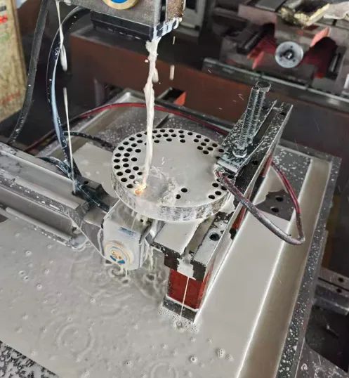
Dielectric fluid flooding the cutting zone during an active wire erosion pass, keeping the discharge gap flushed and cooled.
Key takeaway: independent guide-head articulation is the structural feature that separates large-taper wire EDM eroders from standard vertical-cut machines.
Application Scenarios and Selection Criteria
Wire EDM eroders serve tool and die shops, mold makers, aerospace component suppliers, medical device machinists, and stamping die manufacturers, largely because these industries routinely work with hardened alloys and require tight dimensional tolerances that conventional milling cannot always guarantee. A stamping die shop, for example, relies on a wire cut EDM machine to produce punch and die clearances with consistent, repeatable accuracy across long production runs. Aerospace and medical suppliers often favor wire erosion machining for small, geometrically complex features where the non-contact cutting action avoids inducing stress into thin sections.
Comparing Typical Use Cases Side by Side
Straight-Wall Die and Mold Work
Progressive stamping dies, injection mold inserts, and punch components typically require vertical or near-vertical walls, so a medium-speed or high-speed wire EDM machine is generally sufficient. These jobs prioritize surface finish consistency and dimensional repeatability over extreme angle capability.
Tapered and Draft Angle Components
Extrusion dies, blanking dies with relief angles, and certain aerospace flow-path parts require sidewalls cut at an angle. A large-taper wire EDM eroder with independently steerable upper and lower guides is generally required for this category of work.
When evaluating which category of wire eroder suits a given production line, buyers commonly weigh four factors: the maximum taper angle the part drawings call for, the target surface finish grade, the acceptable cycle time per part, and the range of workpiece thickness the shop regularly processes. A shop that mixes both straight-wall and tapered work sometimes standardizes on a large-taper wire EDM eroder so a single machine platform can cover both job types, reducing the need for multiple dedicated machines.
Key takeaway: matching taper capability, surface finish requirements, and part thickness to the machine class prevents costly re-fixturing or secondary operations.
Detailed Comparison of Wire EDM Machine Series
Before comparing performance visually, it helps to understand what separates these three machine families at a practical level. Medium-speed wire cut EDM machines reuse the wire across multiple passes, which supports finer finishing cuts after the initial rough pass. High-speed wire EDM machines feed molybdenum wire in a single continuous direction at higher travel rates, favoring throughput on simpler two-dimensional shapes. Large-taper wire EDM machines add articulated guide heads and extended axis travel so angled walls can be produced without secondary processing. The radar chart below places these three families side by side across four criteria that buyers most often evaluate.
Illustrative relative positioning of machine families across four buyer-priority criteria (not measured lab data).
Reading the chart from the outside in, the large-taper family extends furthest along the taper capability axis, reflecting its purpose-built guide-head articulation, while its surface finish and precision scores remain comparable to the medium-speed family because both use similar multi-pass finishing logic. The high-speed family extends furthest along the cutting speed axis but sits closer to center on taper capability, consistent with its design focus on straightforward, fast two-dimensional profiles rather than angled geometry. None of the three families dominates every axis at once, which is precisely why shops select between them based on the part mix they actually run rather than assuming one machine class is universally superior. A shop cutting mostly stamping die inserts with vertical walls generally gets more practical value from the speed and finish balance of a medium-speed or high-speed configuration. A shop regularly producing extrusion dies or angled aerospace channels benefits more from the taper axis strength of a large-taper configuration, even if that comes with a different operating rhythm on straight-wall jobs. Surface finish quality on all three families is also influenced heavily by wire diameter, number of finishing passes, and dielectric fluid condition, not the machine family alone. Precision likewise depends on servo control quality, thermal stability of the machine bed, and how well the worktable is maintained over time. Because of these interacting variables, the radar comparison should be read as a starting point for narrowing machine category, not as a substitute for reviewing the specific part drawings and tolerance callouts of the intended job mix. Shops that process a genuinely mixed workload sometimes find that standardizing on a large-taper platform, and simply running it in straight-wall mode for non-tapered jobs, reduces the total number of machine types they need to maintain and program.
Series-Level Feature Comparison
General feature comparison across common wire EDM eroder series categories.
Category
Wire Handling
Typical Focus
Taper Capability
Medium-Speed Wire EDM
Molybdenum wire, reused across passes
Finish quality and repeatability
Standard
High-Speed Wire EDM
Continuous single-direction feed
Throughput on 2D profiles
Standard
Large-Taper Wire EDM
Continuous feed, articulated guides
Angled and draft-wall geometry
Extended
Beyond taper angle, shops comparing large-taper wire eroders to standard configurations often look at how wide the taper range is at a given workpiece thickness, since capability generally narrows as material gets thicker. The horizontal bar chart below illustrates this relative positioning at a conceptual level, showing how taper range capability typically widens moving from medium-speed configurations toward dedicated large-taper platforms. This is presented as a general industry reference pattern rather than a specification for any single machine model. Buyers should always confirm exact taper range and thickness limits against a specific machine's published specification sheet before finalizing a purchase decision. Even so, the relative ordering shown here reflects a consistent pattern across the wire EDM eroder market.
Conceptual comparison of relative taper range capability across wire EDM eroder categories (illustrative, not a product specification).
Key takeaway: large-taper wire EDM eroders extend usable taper range the furthest, but the correct choice still depends on the actual part mix a shop runs.
Industry Direction: Automation Adoption in Wire EDM Operations
Alongside machine category selection, shops increasingly weigh how much automation a wire EDM eroder platform supports, since unattended run time directly affects overall shop throughput. Automation on modern wire cut EDM machines can include automatic wire threading after a break, programmable multi-pass finishing routines, and remote job monitoring. These features reduce the amount of operator intervention needed during a shift and allow a single technician to oversee multiple machines running simultaneously. The line chart below sketches a general, illustrative pattern of how automation-related feature adoption has trended across the wire EDM equipment sector over roughly the past decade. It is presented as a conceptual trend rather than a specific measured statistic from any single source.
Conceptual, illustrative trend of automation-related feature adoption across wire EDM eroder platforms over time.
The upward slope shown here reflects a general direction rather than a precise industry figure, but it aligns with a pattern many tool room managers describe anecdotally: automation features that were once optional upgrades are now commonly included on mid-range and higher wire EDM eroder configurations. Automatic wire threading, in particular, has moved from a premium feature to a near-standard expectation, since it directly reduces downtime after wire breaks on long, unattended cutting cycles. Programmable multi-pass finishing routines have also become more accessible, letting operators define rough and finish passes once and reuse that logic across similar part families without reprogramming each time. Remote monitoring capability has grown alongside broader factory connectivity trends, allowing supervisors to check cutting status without walking the shop floor. None of this removes the need for skilled operators, since programming complex tapered geometry and diagnosing discharge instability still requires hands-on expertise. What automation does change is how much routine, repetitive attention a machine needs during a normal production run, freeing operators to manage several machines or handle higher-value programming tasks instead. Shops evaluating a new wire cut EDM machine purchase increasingly ask about these automation features specifically, alongside the more traditional questions about taper range and surface finish grade. For a shop planning capacity for the next several years rather than just the next job, automation capability is worth weighing as seriously as raw cutting speed. This is especially true for shops running lights-out or extended unattended shifts, where a wire break that goes unaddressed for hours has a much larger cost than the same event during a staffed shift. Ultimately, automation adoption trends reinforce a broader point already made in the comparison sections above: machine selection should reflect how the equipment will actually be used day to day, not just its headline specifications.
Key takeaway: automation features such as automatic wire threading have shifted from optional extras to a practical expectation on modern wire EDM eroder platforms.
Matching Wire EDM Machine Selection to Your Application
Choosing the right wire EDM machine depends on more than cutting speed or purchase price alone. The best-fit configuration should match the workpiece material, the required dimensional accuracy, the part geometry, expected production volume, and a shop's longer-term manufacturing goals. Different industries, and often different jobs within the same shop, call for different wire EDM configurations, which is why it is worth revisiting how a specific application maps back onto the machine families already compared above before finalizing a purchase decision.
For Precision Mold Manufacturing: Choose Medium-Speed Wire EDM
For mold manufacturers producing precision inserts, punches, dies, and other complex tooling components, a medium-speed wire EDM machine is usually the preferred starting point. Medium-speed wire EDM machines use multiple cutting passes to balance machining efficiency with a strong surface finish and dimensional accuracy, which is exactly the balance precision mold work demands. This approach suits shops where customers expect stable precision, reduced downstream polishing work, and consistent machining quality from one production run to the next.
Typical applications include:
Precision molds
Stamping dies
Plastic injection mold components
High-tolerance mechanical parts
Carbide and hardened steel machining
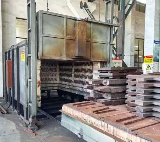
Hardened tool steel plates staged after heat treatment, the kind of material medium-speed wire EDM is regularly used to finish to close tolerance.
POOSN PSC Series medium-speed wire EDM machines are designed for shops that need higher machining quality and stable, repeatable performance in precision manufacturing environments, extending the medium-speed lineup already outlined in the series comparison earlier in this article.
Surface finish on a medium-speed wire EDM machine is not fixed by the machine alone; it is shaped largely by how many finishing passes are programmed after the initial rough cut. Each additional pass removes a thinner layer of material at lower discharge energy, which progressively smooths the kerf wall and tightens the achievable tolerance. This multi-pass logic is central to why medium-speed platforms are favored for precision mold and die work over single-pass high-speed cutting. The column chart below illustrates, at a conceptual level, how surface roughness typically trends downward as additional finishing passes are added on a multi-pass wire EDM setup. It is presented as an illustrative pattern reflecting general multi-pass EDM behavior rather than a guaranteed result for any specific machine, material, or wire diameter.
Conceptual surface roughness trend across successive passes on a multi-pass wire EDM setup (general reference range, not a fixed specification).
Reading the chart from left to right, the first bar represents the rough cut pass, which prioritizes material removal speed over surface quality and typically leaves a comparatively rough kerf wall. The second bar reflects a first finishing pass, where discharge energy is reduced and the wire trims a thin skin layer to correct dimensional error left by the rough cut. The third and fourth bars represent additional finishing or skim passes, each removing progressively less material at progressively gentler discharge settings, which is why surface roughness continues trending downward but with smaller improvements at each step. This pattern is exactly why precision mold and die shops lean toward medium-speed wire EDM configurations that support wire reuse across several passes, rather than a single-pass high-speed setup better suited to rougher two-dimensional profiles. The trade-off is cycle time: each additional finishing pass adds machining minutes, so shops generally stop adding passes once a part reaches the tolerance and finish grade the drawing calls for, rather than always running the maximum number of passes available. Wire diameter, dielectric fluid condition, and workpiece material all influence exactly where each bar lands, so the values shown here should be read as a general reference range rather than a fixed specification for any particular machine. Thicker or harder workpiece material generally needs more passes to reach the same finish grade compared with a thinner or softer section. Shops producing plastic injection mold components with tight parting-line tolerances, for example, often program three or more finishing passes specifically because downstream polishing time is expensive and a better as-cut finish reduces that manual labor. Carbide and hardened tool steel machining follows a similar logic, since these harder materials can be more sensitive to discharge energy and benefit from a gentler, more gradual finishing sequence. High-tolerance mechanical parts destined for assemblies with tight fits also tend to justify the extra pass count, since dimensional consistency there directly affects downstream assembly yield. Ultimately, the number of passes programmed on a medium-speed wire EDM machine is a practical lever operators adjust job by job, balancing the finish grade a part requires against the cycle time a production schedule allows.
Key takeaway: precision mold work generally points toward a medium-speed wire EDM machine, and multi-pass programming, not the machine alone, is what ultimately delivers the tight tolerance and finish grade this work demands.
Maintenance Guidance for Long-Term Machine Reliability
Consistent maintenance is what allows a wire EDM eroder to hold its positioning accuracy over years of production rather than just its first months in the shop. Dielectric fluid condition deserves particular attention, since contaminated or depleted fluid directly affects discharge stability, surface finish quality, and wire consumption rate. Wire guides and contact points wear gradually from constant wire travel, so periodic inspection catches replacement needs before they show up as inconsistent cut quality or unexpected wire breaks. Worktable rails and ball screws also require regular cleaning and lubrication, since accumulated debris in these areas is a common, preventable cause of gradual accuracy drift.
The chart below breaks down where routine maintenance time is typically spent on a wire cut EDM machine, based on general shop practice rather than a specific timed study, so shops can plan maintenance schedules around the areas that most often need attention.
General allocation of routine maintenance time across common task categories (illustrative shop-practice pattern).
Legend for the maintenance time allocation chart above.
Maintenance Task
Typical Share of Maintenance Time
Dielectric fluid and filter servicing
30%
Wire guide and tension inspection
25%
Electrical contact and wire feed check
20%
Bed and rail cleaning
15%
Software and calibration checks
10%
Dielectric fluid and filter servicing consistently claims the largest share of routine maintenance attention, which reflects how directly fluid cleanliness affects every cut the machine makes. When filtration is neglected, eroded particles recirculate through the tank and can cause inconsistent discharge behavior, visible as uneven surface finish or unexplained wire breaks partway through a job. Wire guide and tension inspection ranks second because these components experience continuous mechanical wear from wire travel and directly influence positioning accuracy along the cut path. Electrical contact and wire feed inspection matters because degraded contacts introduce resistance variation that can destabilize discharge timing, particularly on longer unattended runs. Bed and rail cleaning, while smaller in typical time share, has an outsized long-term effect on machine accuracy, since accumulated debris in these areas tends to cause slow, hard-to-diagnose positioning drift rather than an obvious fault. Software and calibration checks round out the list and are typically the fastest of the five categories, but skipping them for extended periods can allow small offset errors to compound over many jobs. Shops that build a maintenance calendar around this general allocation tend to catch developing issues before they interrupt production, rather than reacting only after a wire break or a rejected part reveals a problem. It is worth noting that actual time spent on each category will vary by shop environment, water quality, workload intensity, and how many hours per week the machine runs. A shop running near-continuous multi-shift production will generally need to service dielectric fluid and filters more frequently than the general pattern shown here suggests. Pairing a documented maintenance log with the manufacturer's recommended service intervals gives the most reliable basis for scheduling, rather than relying on a fixed calendar date alone. Positioning accuracy testing at commissioning, and periodically thereafter, remains one of the most direct ways to confirm that accumulated wear has not started to affect part quality.
Key takeaway: dielectric fluid management and wire guide inspection together account for over half of routine wire EDM eroder maintenance attention, and neglecting either is a common source of avoidable downtime.
Choosing a Reliable Wire EDM Eroder Manufacturer
When evaluating a wire EDM eroder manufacturer or supplier, shops generally look beyond the spec sheet toward how the machine is engineered, tested, and supported after purchase. Consistency in manufacturing process matters here, since two machines built to the same nominal specification can behave differently in the field if positioning accuracy is not verified on every unit before it ships. A manufacturer with in-house research, development, and production capability is often better positioned to refine wire feed control, guide-head articulation, and control software over successive product generations, rather than relying entirely on third-party subsystems.
Taizhou Xinchengyang Machinery Manufacturing Co., Ltd is one example of a manufacturer built around this kind of focused specialization, with years of experience concentrated specifically on electrical discharge machining and special processing equipment. The company's product range spans the categories discussed throughout this article: the PS-C and DK77-BC series cover medium-speed wire-cutting EDM needs, the DK77-A and DK77-B series address high-speed wire-cutting applications, and the DK77-D series is built for large-taper wire-cutting work. Each machine tool produced by the company undergoes positioning accuracy testing before leaving the factory, which reflects the broader industry point made earlier in this article about why accuracy verification matters for long-term reliability. The company's products are distributed nationwide, with select models reaching customers across Southeast Asia, West Asia, Europe, and the Americas, giving it experience supporting wire EDM eroders across a range of operating environments and part applications.
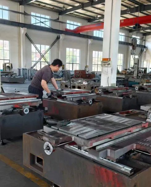
Machine beds being fitted and checked on the production floor prior to final assembly and accuracy testing.
For shops comparing suppliers, this kind of focused product range, covering medium-speed, high-speed, and large-taper categories under one manufacturer, can simplify sourcing for shops that expect their part mix to evolve over time. A wire EDM eroder manufacturer that also functions as a wholesaler or supplier to distributors benefits from feedback across a wider base of installed machines, which in turn can inform ongoing product refinement. Shops evaluating any wire EDM equipment supplier should ask specifically about positioning accuracy testing procedures, since this single quality control step has an outsized influence on how consistently a machine will perform once it reaches the shop floor.
How to Choose the Right Wire EDM Machine for Your Application Choosing the right Wire EDM machine depends on more than just cutting speed or machine price. The ideal configuration should match the workpiece material, required accuracy, part geometry, production volume, and long-term manufacturing goals. Different industries and applications require different Wire EDM solutions, which is why understanding the differences between machine series is essential before making a purchase decision. For Precision Mold Manufacturing: Choose Medium-Speed Wire EDM For mold manufacturers producing precision inserts, punches, dies, and complex tooling components, a medium-speed Wire EDM machine is usually the preferred choice. Medium-speed Wire EDM machines use multiple cutting passes to balance machining efficiency with excellent surface finish and dimensional accuracy. They are suitable for applications where customers require stable precision, reduced polishing work, and consistent machining quality. Typical applications include: · Precision molds · Stamping dies · Plastic injection mold components · High-tolerance mechanical parts · Carbide and hardened steel machining POOSN PSC Series medium-speed Wire EDM machines are designed for customers who need higher machining quality and stable performance in precision manufacturing environments.
Frequently Asked Questions
Q1: What is the difference between a medium-speed and a high-speed wire EDM eroder?
A medium-speed wire cut EDM machine reuses the wire across multiple passes, which supports finer finishing on the part. A high-speed wire EDM machine feeds wire in a single continuous direction, favoring faster throughput on straightforward two-dimensional profiles rather than repeated finishing passes.
Q2: When does a shop actually need a large-taper wire EDM eroder?
A large-taper wire EDM eroder becomes necessary when part drawings call for angled or draft sidewalls, such as extrusion dies or certain aerospace flow-path components. Shops that only cut vertical-wall parts generally do not need the extended taper range this category provides.
Q3: What role does the dielectric fluid play in wire erosion machining?
Dielectric fluid cools the cutting zone, flushes away eroded particles, and helps stabilize each electrical discharge along the cut path. Poor fluid condition is one of the most common causes of inconsistent surface finish and unexpected wire breaks on a wire EDM eroder.
Q4: How often should wire guides be inspected on a wire cut EDM machine?
Wire guides should be checked on a routine schedule aligned with the machine's usage intensity, since continuous wire travel gradually wears these contact points. Shops running near-continuous production generally need more frequent inspection than shops running the machine only intermittently.